Technology Workshops
Amlinelliad o'r pwnc
-
-
f you have a reliable Internet connection, you should use the online IDE (Arduino Web Editor). It will allow you to save your sketches in the cloud, having them available from any device and backed up. You will always have the most up-to-date version of the IDE without the need to install updates or community generated libraries.
-
The open-source Arduino Software (IDE) makes it easy to write code and upload it to the board. It runs on Windows, Mac OS X, and Linux. The environment is written in Java and based on Processing and other open-source software.
This software can be used with any Arduino board.To get step-by-step instructions select one of the following link accordingly to your operating system.
- Windows
- Mac OS X
- Linux
- Portable IDE (Windows and Linux)
Choose your board in the list here on the right to learn how to get started with it and how to use it on the Desktop IDE.
-
Almost in all the schools, colleges and universities students don't have administrator privileges, so they don't have write access in some folders. This leads to some problem in using the Arduino Software (IDE) since your preferences and sketchbook are saved in one of those folders. Using a portable version of the IDE you can overcome this problem.
-
circuito.io allows users to design and create Arduino Circuit Diagrams. Simply drag and drop your components onto your virtual board and the system will show you how to wire everything together and automatically calculates the resistors that will be required and where they need to be situated.
-
-
-

-
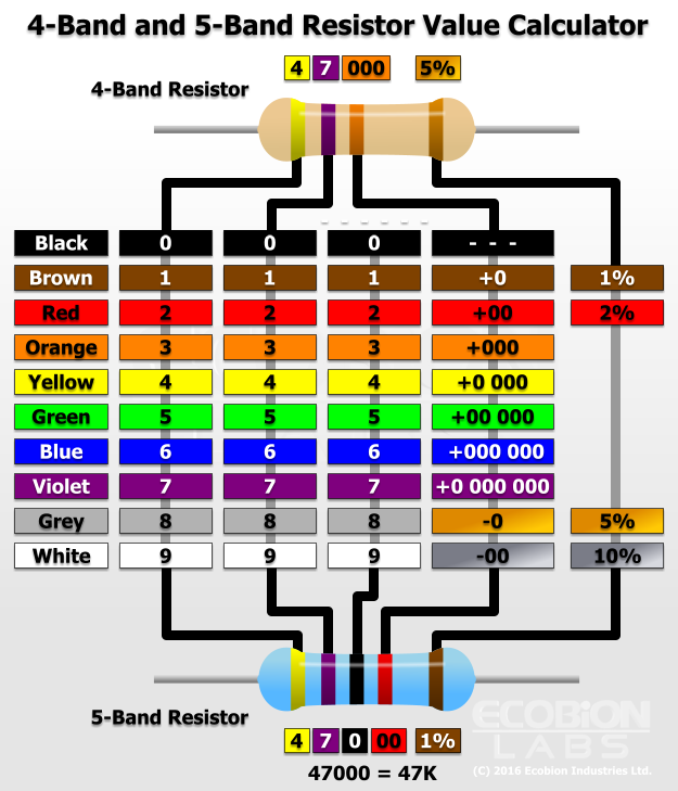
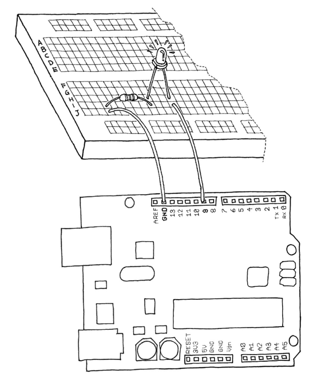
Required Resistor: 270 ohm (Red, Violet, Brown)

-
Analog Input
As you learned in the previous section, Arduino is able to detect whether there is a voltage applied to one of its pins and report it through the digitalRead() function. This kind of either/or response is fine in a lot of applications, but the light sensor that we just used is able to tell us not just whether there is light, but also how much light there is. This is the difference between an on/off sensor (which tells us whether something is there) and an analogue sensor, whose value continuously changes. In order to read this type of sensor, we need a different type of pin.
In the lower-right part of the Arduino board, you’ll see six pins marked “Analog In”; these are special pins that can tell us not only whether there is a voltage applied to them, but if so, also its value. By using the analogRead() function, we can read the voltage applied to one of the pins.
This function returns a number between 0 and 1023, which represents voltages between 0 and 5 volts. For example, if there is a voltage of 2.5 V applied to pin number 0, analogRead(0) returns 512.
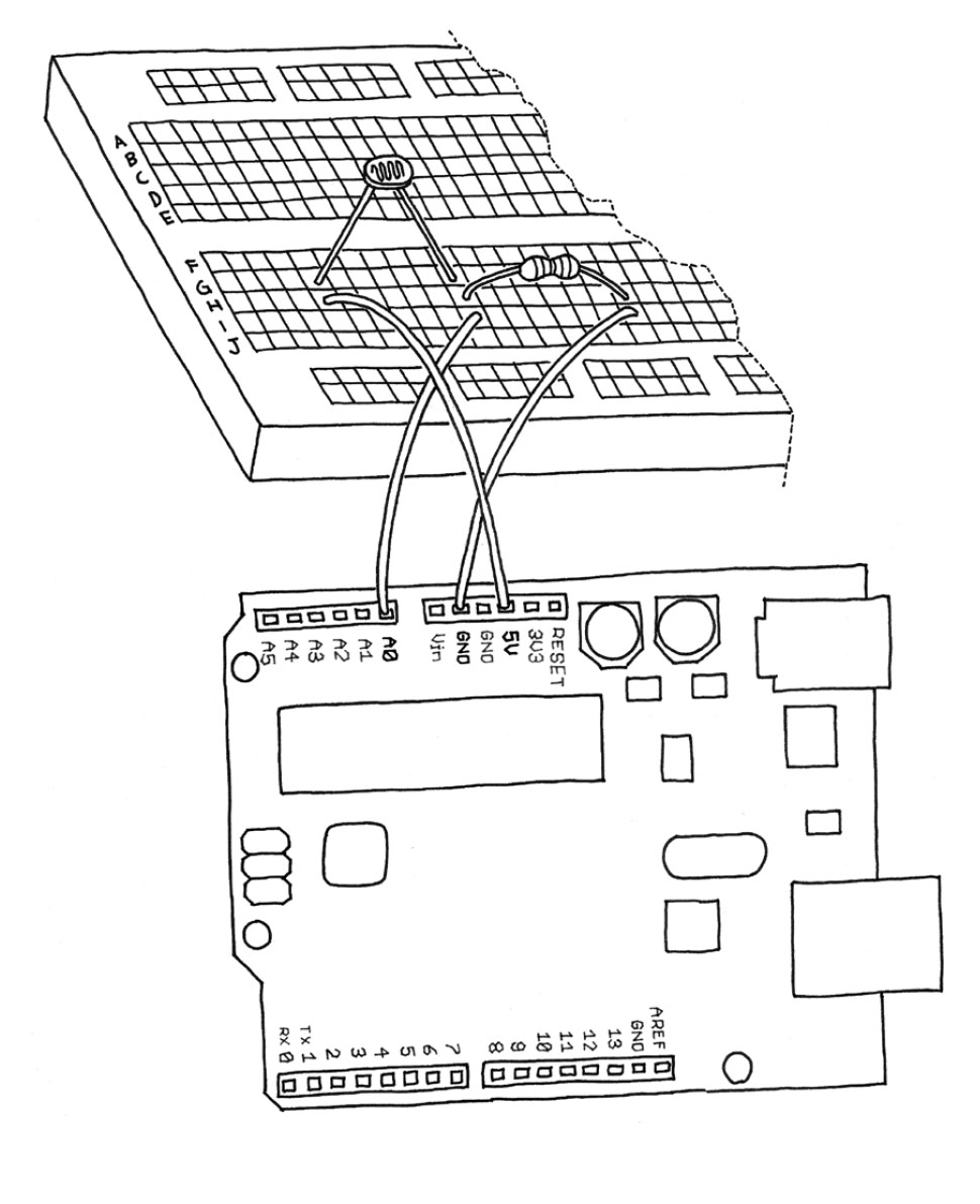
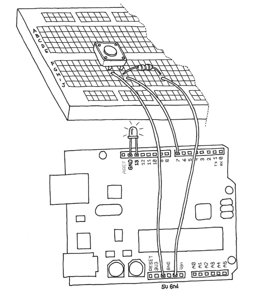
If you now build the circuit that you see in figure, using a 10k resistor, and run the code listed in Example 6, you’ll see the onboard LED (you could also insert your own LED into pins 13 and GND as shown in “Blinking an LED” example, blinking at a rate that’s dependent upon the amount of light that hits the sensor.
Required Resistor: 10k

-
In some cases we may need to capture the data from an analogue sensor to determine its value, this can been used with other statements to provide different triggered events.
-
Please download the following code to test the Serial Monitor
-
-
The following Arduino Sketch demonstrates how a Piezo Buzzer can be activated to create audible sound at different frequencies.
Challenge: Create your own tune and see if someone can recognise the tune.
-


